Wednesday, November 30, 2016

ESP 32 - getting to Blinky


To get to a blinking LED with the ESP32 and the Arduino-IDE you have to Install all needed Software and also wire up your ESP32 if you not using a development Board.

My CP2102 USB to UART Converter is not capable to provide enough current at the 3.3V Output for the ESP32 so i have to use a voltage regulator (i.e. AMS1117 3.3) with some capacitors (not in the Picture).

ESP32 - sample configuration
And to use the basic example sketch blink.ino we have to install all the Software:

(example using a Ubuntu 16.4 Linux environment):


see https://www.arduino.cc

    Download https://downloads.arduino.cc/arduino-1.6.12-linux64.tar.xz

    mkdir arduino
    cd arduino
    cp ~/Downloads/arduino-1.6.12-linux64.tar.xz .
    tar xJf arduino-1.6.12-linux64.tar.xz
    cd arduino-1.6.12/
    ./install.sh


see https://github.com/espressif/arduino-esp32/blob/master/README.md


    https://github.com/espressif
    https://github.com/espressif/arduino-esp32

    cd hardware
    mkdir espressif
    cd espressif
    git clone https://github.com/espressif/arduino-esp32.git esp32

    cd esp32/tools
    python get.py


After all the Software installation you have to enable the ESP32 to download the new Firmware via UART by pulling GPIO0 to ground (pressing flash button) and also do a reset by pulling EN to ground far a short time.


rst:0x1 (POWERON_RESET),boot:0x3 (DOWNLOAD_BOOT(UART0/UART1/SDIO_REI_REO_V2))
waiting for download


Then you can use the Upload the blink.ino sketch via upload Button to your ESP32.

My Arduino Tool Configuration:

Board: ESP32 Dev Module
Flash Frequency: 80ß MHz
Upload Speed: 115200
Port: /dev/ttyUSB0

(If you not using the serial monitor from Arduino-IDE i.e. putty you have to close your tool before uploading).

The GPIO Pin 13 is configured as output and is switched on and off by delay some ms - the LED is blinking. But you have to limit the current used by the LED to protect the GPIO Pin and also the LED by using i.e. a 220 Ohm resistor.

Happy blinking.

Further information on Youtube:

ESP32 - Installing Software:
https://youtu.be/rP9p0MzxSos

ESP32 - Getting to Arduino blinky:
https://youtu.be/_eu39u45XVk


Tuesday, October 4, 2016

nRF51822: secure DFU OTA via BLE

Secure Device Firmware Update Over the Air via Bluetooth Low Energy


secure DFU OTA via BLE

How to update your firmware without physical touch it? Maybe you could not reach your Sensor or Beacon? But is there a secure way without open your Hardware to the public?
secure Device Firmware Update Over the Air via Bluetooth Low Energy
To use secure DFU OTA your firmware for your BLE hardware have to be encrypted. And you need a bootloader with a Bluetooth Service that can decrypt the transfered data (firmware). in the case of the nordic SDK 12.0.0.0 the bootloader use eliptic curve cryptography (curve_secp256r1, micro-ecc from Kenneth MacKay). For the encryption a private key is used and for the decryption the public key. So the secure bootloader have to know the public key.


Building the APP and the secure Bootloader

To setup your secure DFU OTO via BLE you first have to generate the private/public key. You can use the nrfutil from nordic. But to use the tool you need python and pip (pip installs python packages).
On ubuntu you can use this to install and upgrade:

    sudo apt-get install python-pip
    pip install --upgrade pip

and install nrfutil (for me only the sudo install works, and ignored all warnings):

    sudo pip install nrfutil

Generate Private Key with nrfutil

Next step: generate the private and public keys with nrfutil:

    nrfutil keys generate my_secret_private_key.pem
and output the public key code for the bootloader:


        nrfutil keys display --key pk --format code my_secret_private_key.pem
    /** @brief Public key used to verify DFU images */
    __ALIGN(4) const uint8_t pk[64] =
    {
    ....
    };

copy the output to dfu_public_key.c in your secure bootloader directory.


Before you can build your bootloader firmware you have to check the used RAM, unfortunately the bootloader need at least 32kB (i.e. more then 16kB) so not all nRF51822 chip variants can be used. And with the SDK 12.0.0.0 the secure bootloader only works with the S130 Softdevice (i.e. S132 for nRF52832).


the bootloader need at least 32kB RAM

Beside the nordic SDK 12.0.0 you need the micro-ecc library:

        git clone https://github.com/kmackay/micro-ecc micro-ecc
 and in the linker-file the memory settings could look like this:

MEMORY
{
  FLASH (rx) : ORIGIN = 0x35C00, LENGTH = 0xA000
  RAM (rwx) :  ORIGIN = 0x200025E0, LENGTH = 0x5A20
  NOINIT (rwx) :  ORIGIN = 0x20007F80, LENGTH = 0x80
  BOOTLOADER_SETTINGS (rw) : ORIGIN = 0x0003FC00, LENGTH = 0x0400
  UICR_BOOTLOADER (r) : ORIGIN = 0x10001014, LENGTH = 0x04
}

If you have build your secure bottloader hexfile (i.e. dfu_secure.hex). Flash it on your nRF51822 with the S130 Softdevice hexfile (i.e. s130_nrf51_2.0.1_softdevice.hex).

flash the secure bootloade with the S130 softdevice

Nex step is to prepare your firmware for secure DFU OTA via BLE. Agin we use nrfutil with the firmware hexfile (if you not using the debug mode you have to set the firmware version):

nrfutil pkg generate --debug-mode --application dfu_app.hex --key-file ../my_secret_private_key.pem app_package.zip

|===============================================================|
|##      ##    ###    ########  ##    ## #### ##    ##  ######  |
|##  ##  ##   ## ##   ##     ## ###   ##  ##  ###   ## ##    ## |
|##  ##  ##  ##   ##  ##     ## ####  ##  ##  ####  ## ##       |
|##  ##  ## ##     ## ########  ## ## ##  ##  ## ## ## ##   ####|
|##  ##  ## ######### ##   ##   ##  ####  ##  ##  #### ##    ## |
|##  ##  ## ##     ## ##    ##  ##   ###  ##  ##   ### ##    ## |
| ###  ###  ##     ## ##     ## ##    ## #### ##    ##  ######  |
|===============================================================|
|You are generating a package with the debug bit enabled in the |
|init packet. This is only compatible with a debug bootloader   |
|and is not suitable for production.                            |
|===============================================================|

Zip created at app_package.zip


update your firmware securely over the air with bluetooth low energy

Now lets update our firmware secure over the air. Copy the zipfile to your mobile phone (i use android) and start the nRF Connect app. After scanning for bluetooth devices the app should find your device with the running bootloader and the DfuTarg bluetooth service (BLE only).


Discover the DfuTarg Service on your nRF51822 with running bootloader

Next connect to DFUTARG Service. The DFU Icon appears.

Select the Distribution packet (ZIP) with encrypted firmware

choose your prepared ZIP-File

Start the DFU

watch the transfer

transfer reach 100%

Firmware is transfered and started, DFUTARG Service will be disconnected

After the transfer your new firmware will be started automatically. But this in case means that the bootloader will by stopped an the bluetooth service (DfuTarg) will not longer be available.

 An other way is to use the DFU tool inside the nRF Toolbox app:


using the DFU from nRF Toolbox

select you ZIP-File and your secure DfuTarg bootloader device.

start secure DFU OTA via BLE

watch the transfer

transfer is ended, and DFU service will be disconnected


successfully and securely updated your firmware


you can also update the bootloader the softdevice and/or the firmware
In my case the multiple packages don't work, because they don't fit in to the memory of the nRF51822.

For a practical demonstration you can watch the video:

https://youtu.be/T80kzxu7M04

Friday, September 23, 2016

nRF52832: first steps with ST-Link V2 and openocd

The motivation

Let's try one of the best low power bluetooth and nfc SoCs on the market.

The ordering
First we need a development board and a programmer.

So we search some sources for nRF52832 development boards:
(all pricerates today 2016.09.23)

digikey: ~39$ (not including tax and shipping, programmer included)
mouser: ~39$ (not including tax and shipping, programmer included)
aliexpress: ~20$ (including shipping, for me no tax and custom dues, no sensors, no programmer)


Now we search for a programmer:

digikey: ~90$ (not including tax and shipping)
mouser: ~90$ (not including tax and shipping)
aliexpress: ~2$ (including shipping)

Sorry my development budget is small. So give aliexpress a try. 3 weeks later (cheap shipping included) we have a development suite ready.

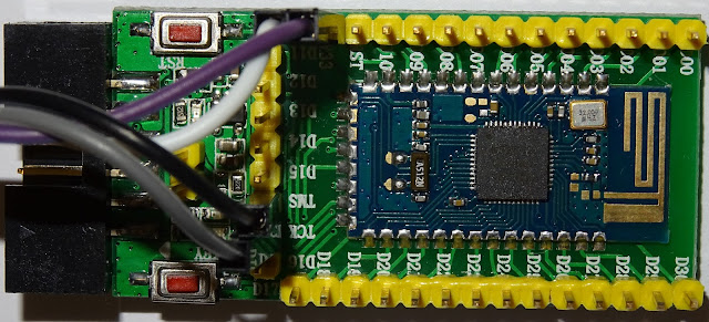
aliexpress nRF52832 board

nRF52832-QFAA SoC ARM Cortex M4


ST-Link V2 Programmer (genuine? work!)


The Hardware

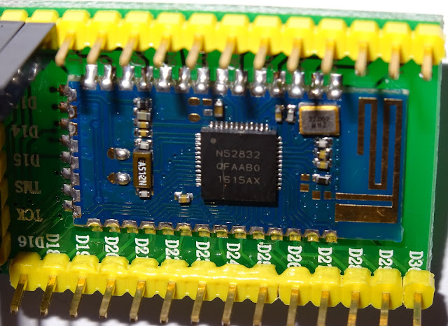
The seller give no instruction for the board so we have to use some inspection and a continuity tester to follow the traces with help from nordics nRF52832-QFAA reference layout. So we find the Pins for SWDIO and SWCLK -> SWCLK goes to TCK and SWDIO goes to TMS and we use 3.3V and GND.


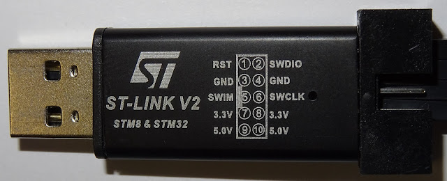
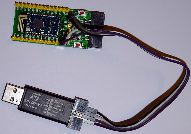
ST-Link V2 and nRF52832 wired up

The Software

- ST-Link V2 

I use ubuntu 16.04 so the ST-Link V2 don't PnP out of the box, we need some more packages:

    sudo apt-get install git
    sudo apt-get install autoconf
    sudo apt-get install libusb-1.0-0-dev

Then we build the drivers for the ST-Link V2 from source:

   git clone https://github.com/texane/stlink stlink.git
   cd stlink.git/
   ./autogen.sh
   ./configure
   make


Then we copy the driver and udev rules:

    sudo cp st-* /usr/bin
    find . -name "*.rules"
    sudo cp ./etc/udev/rules.d/49-stlinkv2.rules /etc/udev/rules.d


And activate the udev rules:

    sudo udevadm control --reload-rules
    sudo udevadm trigger


Let's check:

    lsusb

        Bus 001 Device 021: ID 0483:3748 STMicroelectronics ST-LINK/V2

       dmesg

[0] usb 1-7: new full-speed USB device number 21 using xhci_hcd
[0] usb 1-7: New USB device found, idVendor=0483, idProduct=3748
[0] usb 1-7: New USB device strings: Mfr=1, Product=2, SerialNumber=3
[0] usb 1-7: Product: STM32 STLink
[0] usb 1-7: Manufacturer: STMicroelectronics
[0] usb 1-7: SerialNumber: 6


- openocd

Now we need openocd to use the programmer to flash our nRF52832 firmware:

    git clone git://git.code.sf.net/p/openocd/code openocd-code


And we need some patches for the nRF52832 (more info on devzone.nordicsemi.com and openocd.zylin.com):

 
git pull http://openocd.zylin.com/openocd refs/changes/15/3215/2

Then i added to openocd-code/src/flash/nor/nrf52.c in line 133 to fit my nRF52832 hardware:

    {
        .hwid        = 0x00C7,
        .variant    = "QFN48",
        .build_code    = "B00",
        .flash_size_kb    = 512,
    },


Let's build and install openocd:

    cd openocd-code/
    ./bootstrap
    ./configure
    make
    sudo make install


An openocd config-file (i.e. openocd_nrf52.cfg) can look like this:


 #nRF52832 Target
source [find interface/stlink-v2.cfg]

transport select hla_swd

source [find target/nrf52.cfg]


And test our board:

     openocd -d2 -f openocd_nrf52.cfg


Open On-Chip Debugger 0.10.0-dev-00322-g406f4d1-dirty (2016-09-23-11:47)
Licensed under GNU GPL v2
For bug reports, read
    http://openocd.org/doc/doxygen/bugs.html
debug_level: 2
Info : The selected transport took over low-level target control. The results might differ compared to plain JTAG/SWD
adapter speed: 10000 kHz
Info : Unable to match requested speed 10000 kHz, using 4000 kHz
Info : clock speed 4000 kHz
Info : STLINK v2 JTAG v17 API v2 SWIM v4 VID 0x0483 PID 0x3748
Info : using stlink api v2
Info : Target voltage: 3.273018
Info : nrf52.cpu: hardware has 6 breakpoints, 4 watchpoints


Connect with telnet and cleanup our chip (get rid of all test stuff):

     telnet localhost 4444

Trying 127.0.0.1...
Connected to localhost.
Escape character is '^]'.
Open On-Chip Debugger
> reset halt
nrf52.cpu: target state: halted
target halted due to debug-request, current mode: Thread
xPSR: 0x01000000 pc: 0x00000b58 msp: 0x20010000
> nrf52 mass_erase
> reset
> exit
Connection closed by foreign host.


- GNU ARM Compiler

Next step get the GNU ARM Compiler to build our firmware:

Download ready packages from launchpad.net.
I use this linux version gcc-arm-none-eabi-5_3-2016q1-20160330-linux.tar.bz2


Unpack with

     tar xvjf gcc-arm-none-eabi-5_3-2016q1-20160330-linux.tar.bz2


- Nordic SDK 12.0.0

 Download the package from developer.nordicsemi.com:

    actual release nRF5_SDK_12.0.0_12f24da.zip
   
    and unpack:


      unzip nRF5_SDK_12.0.0_12f24da.zip


The Firmware

Let's start with blinky (all sourcecode available in github.com/pcbreflux) :

On our nRF52832 development board there are  two useable LEDs. After some tracing we discover they are on GPIO pin 30 and GPIO pin 31.


So our C - program can look like this:

#include <stdlib.h>
#include "nrf_delay.h"
#include "nrf_gpio.h"

const uint32_t led_pin1 = 31;

/**
 * @brief Function for application main entry.
 */
int main(void) {

    // setup
    // Configure LED-pin as outputs and clear.
    nrf_gpio_cfg_output(led_pin1);
    nrf_gpio_pin_clear(led_pin1);

    // loop
    // Toggle LED.
    while (true) {
        nrf_gpio_pin_toggle(led_pin1);
        nrf_delay_ms(1000);   // 0.5 Hz
    }
}


Now we need one Makefile:

TEMPLATEROOT = ..

# compilation flags for gdb

CFLAGS  += -O0 -g
CFLAGS += -DBOARD_CUSTOM
CFLAGS += -DNRF52832
ASFLAGS += -g
ASMFLAGS += -DBOARD_CUSTOM
ASMFLAGS += -DNRF52832

LDSCRIPT = $(TEMPLATEROOT)/blank_nrf52832_QFAA.ld

# object files

OBJS =  system_nrf52.o main.o

# include common make file

include $(TEMPLATEROOT)/Makefile.common


For Makefile.common see github.com/pcbreflux.

And our linker-file (blank_nrf52832_QFAA.ld):


SEARCH_DIR(.)
GROUP(-lgcc -lc -lnosys)

MEMORY
{
  FLASH (rx) : ORIGIN = 0x0, LENGTH = 0x80000
  RAM (rwx) :  ORIGIN = 0x20000000, LENGTH = 0x10000
}

SECTIONS
{
  .fs_data :
  {
    PROVIDE(__start_fs_data = .);
    KEEP(*(.fs_data))
    PROVIDE(__stop_fs_data = .);
  } > RAM
} INSERT AFTER .data;

INCLUDE "nrf5x_common.ld"


Build the firmware blinky.hex:

       make 

...
'/home/pcbreflux/nordic/gcc-arm-none-eabi-5_3-2016q1/bin/arm-none-eabi-gcc' -Xlinker -Map=_build/blinky.map -mthumb -mabi=aapcs -L/home/pcbreflux/nordic/nRF5_SDK_12.0.0/components/toolchain/gcc -T../blank_nrf52832_QFAA.ld -mcpu=cortex-m4 -Wl,--gc-sections --specs=nano.specs -lc -lnosys -o _build/blinky.out _build/system_nrf52.o _build/main.o _build/gcc_startup_nrf52.o
'/home/pcbreflux/nordic/gcc-arm-none-eabi-5_3-2016q1/bin/arm-none-eabi-objcopy' -O binary _build/blinky.out                   _build/blinky.bin                  
'/home/pcbreflux/nordic/gcc-arm-none-eabi-5_3-2016q1/bin/arm-none-eabi-objcopy' -O ihex _build/blinky.out                   _build/blinky.hex


and flash blinky.hex to our nRF52832 development board:

       make flash

...

** Programming Started **
auto erase enabled
Info : nRF51822-QFN48(build code: B00) 512kB Flash
Warn : using fast async flash loader. This is currently supported
Warn : only with ST-Link and CMSIS-DAP. If you have issues, add
Warn : "set WORKAREASIZE 0" before sourcing nrf52.cfg to disable it
nrf52.cpu: target state: halted
target halted due to breakpoint, current mode: Thread
xPSR: 0x61000000 pc: 0x2000001e msp: 0x20010000
wrote 4096 bytes from file _build/blinky.hex in 0.207181s (19.307 KiB/s)
** Programming Finished **
** Verify Started **
nrf52.cpu: target state: halted
target halted due to breakpoint, current mode: Thread
xPSR: 0x61000000 pc: 0x2000002e msp: 0x20010000
verified 3120 bytes in 0.041079s (74.171 KiB/s)
** Verified OK **


The nRF51822-QFN48 is just a mislead in our openocd patch (see nrf52.c at line 404).

Summary

Practical demonstration can be found on youtube https://youtu.be/dB4xIs0-Kb4.


Friday, September 2, 2016

nRF51822 mit Rotary Encoder (Drehgeber) und Quadrature Decoder (QDEC)

mechanischer Rotary Encoder (Drehgeber)

Ein mechanischer Rotary Encoder (Drehgeber) ist ein Eingabegerät bei dem durch die Rotation eines Knopfes Signale erzeugt werden die man z.B. zum Einstellen von Anwendungswerten verwenden kann. Den Rotary Encoder kann man meist ohne Endstellung in Uhrzeigerichtung oder gegen Uhrzeigerichtung  drehen.

Die preiswerten Versionen eines Rotary Encoder (Drehgeber) haben meist drei Anschlüsse A,B und C. Wobei die Anschlüsse A und B gegen den Anschluss C geschaltet werden.
Symbolischer Aufbau eines mechanischen Rotary Encoder (Drehgeber)

Signalzeitverläufe
 Wird der Rotary Encoder (Drehgeber) zwischen zwei Einrastpositionen in Uhrzeigerichtung gedreht, sind zunächst beide Anschlüsse A und B nicht mit C verbunden (0). Dann schließt sich zunächst der Anschluss A (1), dann B (1) und dann wird A auch wieder von C gelöst (0) und anschließend B (0). D.h. zwischen einem Wechsel zwischen zwei Einrastpositionen gibt es insgesamt vier Signalwechsel. Beim drehen entgegen der Uhrzeigerichtung sind die Signalverläufe umgedreht.
Beispieltestschaltung
Deutlicher wird dies, wenn wir eine Testschaltung mit Leuchtdioden aufbauen. Sobald sich A bzw. B mit dem Anschluss C verbindet ist der LED Schaltkreis geschlossen und die jeweilige LED (Rot oder Grün) leuchtet.
Testaufbau auf einem Entwicklerboard (Breadboard)
Signalwechsel bei einem Anschluss an den GPIO Port eines Mikrocontrollers
Will man einem Rotary Encoder (Drehgeber) mit einem Mikrokontroller auswerten, müssen die jeweiligen Signalflankenwechsel (Lo to Hi oder Hi to Lo) an einem GPIO Pin mit dem Zustand des jeweiligen anderen GPIO Pin gegenüber gestellt werden um die Drehrichtung zu ermitteln.
Beispielschaltung mit einem nRF51822
 (die LEDs und 220Ω Widerstände können auch gegen 4,7kΩ Widerstände ausgetauscht werden).


Um den Drehungen eines Rotary Encoder (Drehgeber) mit dem nRF51822 auswerten zu können könnte man entweder ständig (mit Mikrosekunden Delay) oder Timergesteuert die  beiden verwendeten GPIO Ports auswerten. Oder wir machen dies mit den GPIOTE vom letzten BLOG. Hierbei müsste dann jedoch immer noch bei einem Flankenwechsel innerhalb eines Interrupts der jeweils andere GPIO Pin abgefragt werden. Wird dann z.B. ein Interrupt bei GPIO Port A durch einen Lo to Hi Flankenwechsel ausgelöst zeigt ein GPIO Port B bei 0 eine Drehung in Uhrzeigerichtung an bei 1 eine Drehung gegen den Uhrzeigersinn.
Doch benötigt diese Art der Auswertung CPU Zeit, da die Interruptroutine nur mit Hilfe der CPU Ausgeführt wird.

Eleganter ist daher die Auswertung mit dem in dem in dem nRF51822/nRF51422 eingebauten Peripheral block, dem Quadrature Decoder (QDEC). Der kann die Signale auswerten und sich über einem Report eine definierte Anzahl von zustandsänderungen Merken ohne die CPU z.B. aus dem Low Power Schlaf zu holen.


/** @brief Function handle qdec events.
 */
static void qdec_event_handler(nrf_drv_qdec_event_t event) {
    if (event.type == NRF_QDEC_EVENT_REPORTRDY) {
        m_accdblread = event.data.report.accdbl;
        m_accread = event.data.report.acc;
        if (m_accdblread==0) {
            m_value += m_accread;
    }
        if (m_value<0) {
        m_value = 0;
    } else if (m_value>100) {
        m_value=100;
    }
        if (m_value != m_last_value) {
            uart_printf("report dbl=%u acc=%d",m_accdblread,m_accread);
                if (m_accread>0) {
            uart_printf("\x1B[1;32m"); // GREEN
                } else {
            uart_printf("\x1B[1;31m"); // RED
        }
            uart_printf(" val=%d\n\r",m_value);
        m_last_value = m_value;
        uart_printf("\x1B[0m"); // DEFAULT color
    }
    }
}

/** @brief Function initialization and configuration of QDEC driver instance.
 */
static void qdec_config(void) {
    uint32_t err_code;

        nrf_drv_qdec_config_t qdec_config = NRF_DRV_QDEC_DEFAULT_CONFIG;
    // Initialize hardware
    err_code = nrf_drv_qdec_init(&qdec_config, qdec_event_handler);
    APP_ERROR_CHECK(err_code);
   
    printf("QDEC testing started\n");
    uart_printf("nrf_drv_qdec_init\n\r");

    nrf_drv_qdec_enable(); // Event and corresponding interrupt are enabled.
    uart_printf("nrf_drv_qdec_enable \n\r");
}


Sourcecode ist über GITHUB verfügbar.
https://github.com/pcbreflux/nordic/tree/master/nRF51822/qdec_rotary_encoder

Weiter Informationen im Video:
https://youtu.be/oqvLRRR_ahs


Thursday, September 1, 2016

nRF51822 mit GPIOTE und TTP229 Touchsensor

Was ist GPIOTE?

Mit GPIO Task und Events können mit den nRF51822 (nRF51422) Signalflaken bzw Signaländerung durch das Auslösen eines Interrupts ausgewertet werden. Hierbei wird dann eine Handler-Rutine angesprochen in der der Signalzustandswechsel ausgewertet werden kann.
nRF51822 und GPIOTE


TTP229 angeschlossen am nRF51822 Entwicklerboard mit UART über USB

Beim TTP229 Capacitive Touch Sensor kann man sich dies zunutze machen um die Tasten-(Flächen-)Berührungen seriell auswerten zu können (die parallele Auswertung wird hier nicht betrachtet). 

TTP229 Modul
Für ein Prototyp können Breadbord freundliche Module erworben werden.


TTP229 von TONTEK
 Zur Vorbereitung kann der 16-Key Modus (aktive LOW über TP2) eingeschaltet bzw. der Multi-Key Modus (TP3 und TP4) aktiviert werden. Siehe auch Datenblatt Seite 9 (http://www.tontek.com.tw/download.asp?sn=726).

16-Key und Multi-key Modus aktivieren.


Der TT229 sendet eine Signalflanke am DV (Datavalid) Pin immer dann, wenn ein oder mehrere (Multi Key Mode) Tasten zur Auswertung bereit stehen.

Über den Clock PIN können dann die einzelnen Informationsbits angefordert werden.

nRF51822 mit GPIOTE und UART über Putty via USB.
Sourcecode ist über GITHUB verfügbar.
https://github.com/pcbreflux/nordic/tree/master/nRF51822/gpiote
https://github.com/pcbreflux/nordic/tree/master/nRF51822/ttp229_gpiote

Weiter Informationen im Video:
https://www.youtube.com/watch?v=TPNjfeJAkrg

Thursday, August 18, 2016

Unterschiede zwischen nRF51822 und nRF51422?

Was ist eigentlich der Unterschied zwischen dem nRF51822 und dem nRF51422?

Laut Nordic Semiconductor ASA handelt es sich bei dem um die gleiche Hardwarearchitektur. Der nRF51822 kann jedoch, im Gegensatz zum nRF51422 kein ANT Protokoll, d.h. alle ANT Beispiele laufen nicht auf dem nRF51822.

 Der nRF51422 ist daher ein Tick teurer. Alle anderen, z.B. Bluetooth, Programme sollten, bei gleicher Hardwaregeneration, auf beiden Chips laufen. Es kann daher auch auf dem nRF51422 entwickelt werden und dann die Firemware in Produktion auf den nRF51822 geflasht werden. Jedoch sollte dies Sicherheitshalber vorher mal überprüft werden!

nRF51422 Modul
nRF51822 Module


Der nRF51822/nRF51422 als iBeacon eine Laufzeitabschätzung mit CR2032 Betrieb

Wer seinen iBeacon (mit nRF51822/nRF51422 Chip) mit einer CR2032 bzw. 3V Knopfzelle betreiben möchte sollte sich auch Gedanken über eine ungefähre Laufzeit machen bzw. darüber wie die Laufzeit ohne sündhaft teure Messgeräte ermittelt bzw. hochgerechnet werden kann.

Ein erster Versuch mit einem Multimeter (Fluke 15B+) zeit jedoch die Grenzen auf, da das Gerat auch im µA (Mikroampre) Bereich 0,0 µA anzeigt.

Mutlimeter 0,0 µA


Mit einem Oszilloskop können Spannungsverläufe in einem Zeitbereich dargestellt werden, daher kann der Strom als Spannungsabfall über einen bekannten Widerstand (z.B. 1Ω) gemessen werden.


Messung


In der Beaconfirmware sollte alle nicht relevanten Teile die einen Einfluss auf den Stromverbrauch haben könnten herausgenommen werden wie z.B. eine LED-Anzeige. Das übriggebliebene Bluetooth Advertising sollte dann auf ein gerade noch annehmbares Intervall begrenz werden (>=1s).

Bluetooth Advertising von 100ms -> hoher Stromverbrauch
Bluetooth Advertising 1s -> noch komfortable, geringerer Verbrauch
Bluetooth Advertising 10s -> nicht mehr komfortable, geringster Verbrauch


Danach kann die Messung und Abschätzung beginnen.

Messung mit Bluetooth Advertising 1s
Messung mit Bluetooth Advertising 2s
Messung eines Bluetooth Advertising - Time 1.000ms

Abschätzung der Laufzeit mit CR2032 Battery:

Laufzeitabschätzung